
Analysis methodology
This document is an updated version of that contractually delivered to CNES GEIPAN in 2008 (in French):
APN & PAN - Méthodologie d’analyse des photos numériques de PAN
If you use Internet Explorer (version 8 or below), click on the Compatibility button (top of the screen) to be able to read special characters in formulas.
Authenticity of the document under analysis
The authentication of a photo or video image is an essential element which should be integral part of any analysis, especially when identification of the phenomenon proves to be impossible.
However, there exists no « miracle turnkey solution » that can state with certainty whether such or such a document is authentic or not. Various methods and techniques may be used in order to bring out possible contradictions, between visual testimony and the documentary evidence for example, but one should keep in mind that an investigator’s personal assessment is inseparable from any authentication attempt.
Besides which, the exponential progression of available technical means allowing falsification of a digital document, and of the new difficulties in the detection of falsification which stem from them, requires that any authentication approach should be conducted in a modest way and quite impartially, bearing in mind that no conclusion may be totally definite.
However, specific tools (IPACO software) allow the establishment of whether a digital photo/video document represents or not an authentic original, based on the analysis of the numerous metadata associated with it, some of them being well documented (in particular EXIF tags), others being less known and more difficult to access, as well as on the CamCAT technical database which is integrated into IPACO.
In silver photography, an original document is necessarily a film (black and white, color negative or slide). In digital photography, a photo/video file is deemed original if it results from a simple direct copy (under Windows, Linux, Mac OS…) of the file originally created in the camera, and if the picture has been shot without activating any processing or inlaying of an on-line option.
Establishment of origin of image under analysis
Within an image, when an object or a phenomenon is not yet identified, the first point to be ideally established is whether this apparent object results or not from a stimulus external to the imaging device.
It is a matter of record that many apparent anomalous « objects » are, in fact, cases of visual artifacts appearing on photographs, created by a variety of internal effects that may arise within the camera:
- in the set of lenses:
- dirt particles, droplets or tiny grains of dust sitting on the front lens of the camera, appearing in the photo as strange objects or as so-called « orbs »
- lens flares, produced inside the camera
- light leaks
- on the photosensitive sensor (film in silver photography, photosite array in digital photography):
- « Star effect » phenomenon on a silver film, due to bad manipulation during development, creating a strange stain on the photograph
- « Black sun » phenomenon, due to oversaturation of the photoreceptors in an area of excessive light, rendering less light than that entering the lens and causing a black round « UFO » (most often in the center of a direct image of the sun)
- « Burned pixel » phenomenon showing a seemingly bright spot (usually green) where there is nothing in the area of the scene
- in the encoding process (destructive compression algorithm) of the image file.
On top of that, as mentioned previously, come all cases of hoaxes and image montages, which modern microcomputing makes easily accessible to everybody.
Demonstrably proving the absence of any external stimulus effectively concludes the analysis of an image.
Physical presence of a material object in the scene
If it can be established that there did exist an external stimulus to the camera, the next stage is to establish whether it was linked to the physical presence of a material object in the scene or, alternatively, to that of an immaterial, purely luminous phenomenon.
In the second case, it could be a natural (atmospheric, meteorological, astronomical) phenomenon or, on the contrary, an artificial one (headlight, laser beam, hologram).
Identification of a phenomenon
Whether the stimulus is from a material object or not, analysis of the documentation aims at identifying its exact nature, in a definite and final way if possible, or – if it is not – with an estimated probability.
Final identification of a phenomenon goes through two successive steps: firstly, to work out an acceptable hypothesis, then finally to demonstrate its relevance.
In practice for the investigator, the first objective is to look for a possible rational explanation, drawing parallels with similar cases or with pre-established lists of already identified stimuli. This step may end up with a credible explanation in itself.
The next step then consists, as far as possible, in establishing the supporting evidence that this is the right explanation, thanks to additional data or to undisputable reasoning.
Characterization of an unidentified phenomenon
In case the nature of the phenomenon can definitely not be identified, the goal of analysis is then to characterize this phenomenon as objectively and as accurately as possible, through quantitative parameters that can be measured on the image.
Possible continuation of investigations will then consist of a classification attempt of the various unexplained files, this being the specific approach for sciences of observation.
TWO COMPLEMENTARY TECHNICAL APPROACHES
There exist two distinct – but not mutually exclusive – approaches to exploit on computer a photographic document that contains an unidentified element. Both approaches are well-known in the military domain of image intelligence, where views of Earth ground captured by remote-sensing satellites, reconnaissance planes or drones are studied by photo-interpreters (or image analysts), for defence purposes.
The first approach may be described as qualitative and subjective. It consists of the interactive « instinctive » manipulation of a digital image, so as to provide food for thought or to establish a possible link with a known environment.
The second one is quantitative and consists of conducting geometric and radiometric mensuration on the image file, relying as much as necessary on available additional data.
Qualitative analysis (Photo-interpretation)
Photo- (or imagery) interpretation of a picture usually consists in displaying it on a screen, whilst « manipulating » it in an interactive way, so as to distinguish details and to bring out possible specific features allowing direct investigation and specific mensuration to be conducted.
As a minimum, this operation will require a few standard interactive processing tools, as can be found in most image viewing or processing software. It will constitute a first step, before that of quantitative analysis, which is addressed in the next paragraph.
In the best case, photo-interpretation will take place in a CAPI (Computer-Aided Photo-Interpretation) environment such as IPACO, enabling the investigator to deal simultaneously with both approaches, qualitative and quantitative.
Quantitative analysis (mensuration and estimation)
mensuration and estimation that can be interactively conducted on a digital image, with a computer, fall under two domains: geometric and radiometric.
Geometric mensuration
This type of mensuration, as indicated by its name, concerns parameters such as: angles, solid angles, distances, heights, surfaces, volumes, velocities.
Calculations make use of the camera’s characteristics, settings chosen for the shot, possible later on-site verification and relative positions of pixels in the image file.
Radiometric mensuration
Useful radiometric mensuration concerns, on one hand, luminance of the different objects observed on the photographic document, expressed through corresponding pixel levels in the 3 primary colors, as well as sharpness of those objects’ contours, which depend on the trajectory of light from the actual object to the photographic sensor (mainly through the atmosphere and the camera’s lenses).
Luminance estimation
Pixel values reflect the apparent luminance of the objects in the photographed scene, as well as dispersion of luminous flux in the 3 primary colors, the whole having possibly been altered by atmospheric propagation effects and by limitations of the optical device.
From such mensuration, one may in principle infer useful information regarding energy emitted, transmitted or reflected by the object, as well as, in certain cases, indications about its distance, taking into account modifications of apparent luminance caused by atmospheric absorption and diffusion.
Sharpness estimation
One may estimate the sharpness of an object’s apparent contour, through analyzing transition of gray levels along a line perpendicular to that contour, and then infer useful information about image deterioration due to a number of possible parameters: relative movement between object and camera, depth of field or atmospheric diffusion.
General environment of the picture
Every picture would have been taken in a given place, at a precise time. Depending on the evolution of the investigation, a good knowledge of the spatio-temporal environment often proves to be essential.
This may put many physical measurable data at stake, such as temperature, atmospheric pressure, horizontal visibility, wind velocity and direction, position of stars in the sky, air traffic, possible forecast of atmospheric re-entries, etc.
In digital imagery techniques, the scene is taken to be that portion of space captured in the field of the camera (solid angle) at the time. In practice, it comprises all that is visible in the picture.
Knowledge of as much information as possible about elements of the scene (actual size, distance from the lens, albedo of reference objects, identity of observed stars or planets, etc.) may be crucial to allow proper analysis of the document.
It is essential to know which camera (or cell phone) model was used for the shot, as well as possible settings chosen by the operator, so as to access those technical parameters required for analysis, the most important of which are listed below. This information is generally provided as part of the ancillary data – or metadata – associated with the standard image format generated by a digital camera.
Optical parameters
The optical part and the settings of the camera are common to all types of cameras, silver or digital, even though value ranges may sometimes differ significantly.
Main optical parameters are listed below.
Focal length
The focal length is the distance between the optical center of the lens and the center of the photo-sensitive surface, when focus is to infinity. In other words, it is the distance between the lens and the image focal plane.
All things being equal, the shorter the focal length, the larger the angular field of view.
If the operator has deliberately focussed on a particular object of the scene, knowledge or assessment of the distance between that object and the lens will enable more accurate geometric calculations on the depth of field.
Aperture
The real aperture of the lens is equal to the diameter of the circular diaphragm through which light flows during exposure time, as it has been set (or preset) for the shot.
The aperture – or diaphragm – is usually defined with the help of a dimensionless factor called relative aperture or f-number, equal to the ratio of the focal length to the real aperture of the diaphragm. The scale of normalized f-numbers forms a geometrical progression with common ratio √ 2:
n = 1,0 1,4 2,0 2,8 4 5,6 8 11 16 22 32 45 64
Depth of field
The depth of field is the range of distance from the lens within which contours of photographed objects of the scene appear sharp (outside of movement blur).
When focus has been set to infinity (the general case), the depth of field spreads from a lower limit called the hyperfocal distance to infinity.
In the case of digital cameras, the lower limit of the depth of field is often in the order of one meter or less, whilst the upper limit is generally to infinity.
Exposure time
Exposure time (sometimes wrongly called speed) is the time during which the shutter remains open to operate the shot. Depending on camera models, this parameter may be set by the operator, or preset.
Flash range
The flash range defines the maximum distance from the camera at which an object of the scene may be lit by the flash.
Optoelectronic parameters
In a digital device, the sensitive surface (sensor) consists of a rectangular photosite (Charge-Coupled Device or CCD) array, sensitive to light, which it converts into electric signals. The electric signal generated by each CCD is stored, to represent one pixel of the full scene displayed on the photo.
The CCD array plays a part equivalent to that of the rectangular portion of the film (typically 24x36 mm) in silver photography.
Color handling is provided through different codes, according to camera models, but it always ends up with three values per pixel, corresponding to the three primary colors: red, green and blue.
Sensor dimensions
Knowledge of the real dimensions of the sensitive surface is crucial to derive angular field from focal length, as well as knowledge of the number of CCDs per row and per column is crucial for angular localization of a point of the scene versus line of sight.
Useful dimensions of the sensor may be provided directly, as part of the camera’s technical data, or they may be calculated from other data, in particular the focal length conversion factor : this coefficient directly provides the ratio of the array dimensions to the reference format 24x36 mm of silver photography (more precisely: the ratio of diagonals).
Sensor sensitivity
Contrary to the case of silver photography, where sensitivity is entirely determined by the film used, sensitivity of a digital camera essentially depends on the surface of its CCD array.
In this respect, consumer cameras, with pixel side length not exceeding 2,8 to 4 μm, have a rather low sensitivity (in the order of 50 ISO or less), while there exist digital cameras equipped with medium or large sensors (pixel side length from 5 to 10 μm) offering far higher sensitivity ranges, reaching thousands of ISO.
The ISO value of a digital camera’s sensitivity may be indicated as part of its technical data, or found in metadata associated with each photo.
Spectral response
The spectral response of silicon sensors is intrinsically very different from that of the human eye, as well as that of silver films. Their sensitivity is very high in red and infrared, medium in green and very low in purple and blue, for which manufacturers need to compensate with various more or less sophisticated techniques.
In the case of a thorough analysis, it may be useful to know the spectral response curve of the camera, in particular when the hypothesis of a contribution of ultraviolet or infrared is considered.
Note: spectral domain is where photography shows its most severe limitations as a tool for analysis of rare luminous phenomena observed in atmosphere. In fact, data that would really be multispectral (or even hyperspectral) would provide far richer scientific information about the origin and nature of sensed light than mere photos in 3 colors (RGB).
From this viewpoint, the use of diffraction lenses, which can be adapted to cameras, provides, superimposed on shots, useful spectral information on luminous sources present in the scene (cf Note technique n° 18 du GEPAN, in French).
A digital photo comes in the form of an image file, in a given standard format (most of the time JPEG). This file generally contains metadata, with various information on camera, shooting date and settings (EXIF, IPTC, XMP metadata).
This image file may be collected, in its original format, in different ways: directly from its physical medium (memory stick), from the camera via a USB connection, or from any other digital medium on which it may have been copied (e.g. CD-Rom, USB stick, etc.)
In actual fact, as long as the file has only been copied, without any format modification (or cheating), the digital medium is irrelevant, since the exploitable information remains strictly the same (as opposed to the case of silver photos, where access to the very original is always crucial, because of the irreversible degradation of information caused by every processing step).
Geometric resolution
Simplifying a little, one may consider that, for a given CCD array size, geometric resolution is a function of the total number of pixels, in rows and in columns.
In general, digital cameras offer to the user a choice between different possible spatial resolutions, expressed in millions of pixels, or megapixels.
The spatial resolution value that was used to shoot a photo under study is an essential piece of data, which may be provided by the operator or found afterwards in EXIF metadata.
Radiometric resolution
Each pixel is coded on a given number of bits, which determines its radiometric resolution. The number of gray levels (luminance) and the number of color hues are directly dependent on that.
Encoding and compression algorithms
Image files are sometimes stored in raw format, in view of future reversible « digital developing », but most of the time they are compressed in an irreversible way in JPEG format, inside the camera.
If the compression mode is destructive, it is termed « lossy », which means leading to a loss of information (as with JPEG). It may result in artefacts appearing on the picture (generally moirés).
Such a deterioration of image quality may then be visible, especially if the chosen compression factor is high.
Metadata
As already mentioned, files generated by a digital camera (generally in JPEG format) contain, besides rows and columns of pixels, a number of ancillary data or metadata (EXIF, IPTC, XMP…). They contain characteristics not only of the file itself, but also of the camera, as well as dating and settings of the shot. Some fields are also reserved, in this format definition, for various additional data, in particular GPS localization.
Extraction of these data – invaluable for analysis – is possible through specialized software, many of which are accessible for free on the Internet. In most cases, metadata are sufficient to conduct analysis, even in the absence of information from the witness on the camera used. The IPACO software enables the analyst to determine, using metadata, whether a digital picture in JPEG format is an original or not, and provides all available elements in order to assess the probability of a fake.
MEASURABLE PARAMETERS ON A PHOTO
Parameters that may be measured from a photo are expressed in two domains: geometric and radiometric.
Geometric parameters – angles, sizes or distances – make use of pixel positions, in rows and columns, while radiometric parameters are calculated from pixel luminance levels.
Photography is based on a principle of conical projection and time integration, which permits representation by a 2-dimensional image of information that occupies a 4-dimensional space (elevation, azimuth, depth and time). It is therefore impossible to reconstruct the whole geometry of a scene from a single photo, except if additional information is available (such as other photos shot from another direction, or data from other sources).
In particular, if the position of pixels in a photo allows (provided other indispensable technical data are available) the calculation of the angular dimensions of an object, an assessment of its real dimensions is only possible if the distance between that object and the camera at shooting time is known or may be estimated.
We shall deal successively with angular distance of a given point from the line of sight (often referred to as the principal axis), and with mensuration of an angular dimension of an object. Then, after a reminder on how to derive a linear dimension from that and from the distance to the lens, we shall review different ways to assess that distance or, at least, a range of possible values.
In order to calculate the angular distance from the line of sight, of a point of the scene represented by point A on the sensor, or the angular distance δ between 2 points of the scene represented by points A and B on the sensor, one needs several geometric data: focal length f used for the shot, and distances d, a and b, measured on the photosensitive medium (silver film or CCD array), defined as follows:
f : focal length
a : measure of distance PA on the sensitive medium
b : measure of distance PB on the sensitive medium
d : measure of distance AB on the sensitive medium
O : optical center of the lens
P : center of the photo on the sensitive medium
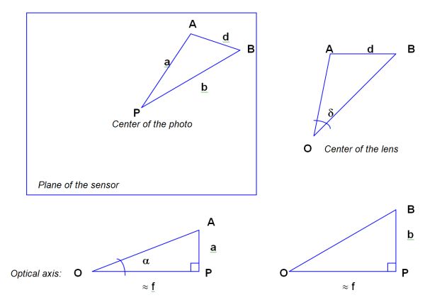
Angular localization of an object in the scene
Inside the solid angle defining the camera angular field at shooting time (i.e. the frame of the scene), it is straightforward to determine the angular distance α of a given point A of the image from the line of sight.
α = arctan (a/f)
In certain cases it will be possible, using additional data, to derive an altitude estimate, if the line of sight is known, and in particular if it is nearly horizontal.
Angular dimensions of an object
Supposing the distance between the points of interest in the scene and the camera is significantly larger than the focal length (which is always true in practice, with the exception of macrophotography), one may assume the following approximation:
OP ≈ f
Putting into practice, on triangle OAB, the generalized Pythagoras’ theorem, one may calculate the angular size of the object δ between points A and B, with the following formula:
2 f2 + a2 + b2 – d2
δ = Arccos [ ___________________ ]
2 √ {(f2 + a2) (f2 + b2)}
To be able to measure – or estimate – the dimension D of an object in a given direction, perpendicular to the line of sight, one must previously know the value – or the estimated value – of 2 pieces of data: the angular dimension δ of the object in that direction and the distance x between that object and the lens.
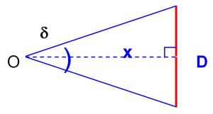
The applicable relation is then:
D = 2x x tan (δ/2)
Estimate of the object’s distance
The distance between an object under study and the lens can of course not be directly derived from the photo, but different analytic approaches can allow an estimate to be made, or at least limits for possible values to be set.
Estimate from other identified and localized objects
If the configuration of elements of the scene allows verification that the distance between the lens and the object under study was comparible to known or measurable limits in its vicinity, one may easily derive a range of possible dimensions for that object, from its angular dimensions.
Depending on cases, reference objects may be buildings, clouds, vegetation or vehicles, etc.
Exploitation of cast shadow
If the object under study casts a shadow visible on the photo, one may try to extract geometric information, in particular if the light source position (the sun is most cases) may be determined in the scene, or if shadows of other objects in that scene may also be brought out.
Analysis of the depth of field
The depth of field defines a range of distance between the lens and an object inside which a photo is sharp (outside movement blur). Therefore it indicates, if the object does appear sharp, possible distance limits between that object and the lens.
This parameter sometimes allows to bring into evidence any incompatibility between sharpness – or blurredness – of an object’s contours on one hand, and its supposed distance from the lens on the other hand (example of « orbs »).
When focus has been set to infinity, which is the case for most photos taken from a digital camera, the depth of field spreads from the hyperfocal distance to infinity. In that case, only objects that are « too close » to the lens may be outside the depth of field, and thus blurred for that reason.
Hyperfocal distance H is calculated as follows:
H = f2 / (n x e)
f : focal length
n : f-number
e : circle of confusion or acceptable sharpness.
Parameter e is rather subjective by nature. In practice, one assigns a value around 0,03 mm in silver photography and, for a digital camera, a value equal to the size of 2 pixels (generally in the order of 0,01 to 0,02 mm).
If focussing has been done on an object located at a distance D, depth of field limits may be calculated as follows:
PdC = Dp – Da
Da = (H x D) / (H + D)
Dp = (H x D) / (H – D)
PdC : depth of field
Da : front distance (lower limit of the depth of field)
Dp : back distance (upper limit of the depth of field)
Atmospheric propagation effects on apparent luminance
In a day picture, particularly one with diffuse lighting (dull sky), the use of light propagation laws (absorption and diffusion) sometimes allows, from mensuration or estimation of apparent luminance based on pixel levels, estimation of a possible distance range between an object observed on the picture and the camera. Some main equations on which this approach is based will be presented later.
Atmospheric diffusion effects on sharpness
Depending on weather conditions, atmospheric diffusion effects on apparent sharpness of contours may be brought out and compared between various reference objects and the analyzed object, which leads to derive a range of possible distances between that object and the camera.
Flash range
On a picture taken by night, if an object appears lit by the flash, its distance from the camera cannot be larger than the flash range.
Transverse velocity of an object
To be able to measure – or estimate – the mean transverse velocity V of an object during a time gap Δt in a given direction, perpendicular to the line of sight, one must previously know the value – or the estimated value – of 2 pieces of data: the angular dimension δ of the piece of trajectory followed by the object during Δt in that direction, and the distance x between that object and the lens. One also needs image data corresponding to the 2 times limiting the time gap Δt.
3 cases may arise:
- 1 photo displays the nearly straight piece of trajectory of a small object moving significantly during exposure time (equal to Δt), shot by a supposedly fixed camera. The angular size of the piece of trajectory may be measured.
- 2 photos of the object under study, successively shot by a supposedly fixed camera, at 2 known times (separated by Δt). Those two images will be summed up and the angular size of the piece of trajectory measured.
- 1 video shot by a supposedly fixed camera, from which 2 images separated by Δt are extracted, bringing back to the previous case.
If the length of the piece of trajectory is equal to L, the tranverse velocity’s value is:
V = L / Δt
Luminance associated with a photographed object is homogeneous with an emitted power per surface unit and per solid angle unit, in the direction of the lens. It is measured in lm/sr/m2 (lumens per steradian per square meter), while correspondence between lumens and watts depends, for each wavelength, on the luminous efficiency of the radiation.
This observed luminance may be due to the object’s own luminous emission, to transmission (transparent or translucent object) or to reflection of light coming from somewhere else, in particular from the sun.
In the case of a non-luminous object, one may assess its albedo: this is the fraction of received luminous flux reflected by the object, the value of which extends from 0, for a theoretical black body, to 1, for a white body. Evaluation of albedo will sometimes, through comparisons, provide indications on the material which makes up or covers the object under study.
The luminous flux F (expressed in lumens) – emitted, transmitted or reflected by the object – is simultaneously modified in two ways by the surrounding atmosphere:
- Atmospheric propagation, between object and camera, leads to attenuation due to atmospheric absorption by air molecules, along a Bouguer line:
F = F0 10-αx
where α is the extinction coefficient and x the thickness of the crossed atmospheric layer.
α value depends on weather conditions and on the wavelength, whereas αx represents the optical density of the considered atmospheric layer.
For light sources located beyond the atmosphere (such as astronomical objects and satellites), the atmospheric total thickness is crossed, the value of which only depends on the zenital distance of the source. The source intensity then varies according to that zenital distance, following a « Bouguer line ».
- In the case of day photos, the proper luminance L of an object located in the low atmosphere, at a distance x from the lens, is attenuated by atmospheric absorption as previously indicated, thus adding a contribution of atmospheric diffusion of daylight.
If LH represents sky luminance on the horizon (x ® ¥), apparent luminance L’ of the object is given by the relation:
L’ = 10-αx L + (1 - 10-αx) LH
where the first term represents the extinction of light coming from the object, and the second one the contribution of atmospheric diffusion.
If it is a black object (or very dark), the formula simplifies as follows:
L’ = (1-10-αx) LH
In the particular case of an object of albedo R, under a uniformly dull sky, we have:
L’ = [1 – (1 – R/2) 10-αx ] LH
Directly measurable data that quantify light received by a given pixel in the digital image are its gray level (along the black to white axis) and its respective luminance levels in the 3 primary colors axes (red, green, blue). Those values characterize the apparent luminance of corresponding points of the scene. In silver photography, as well as in digital in the case of the RAW format, one may sometimes establish a correspondence formula – more or less empirical – between luminance and gray level, through luminance calculations. Unfortunately this becomes practically impossible with JPEG format, because of all the optimization real-time processing performed inside the camera before storing the image (RGB demastering, delinearization with application of gamma factor, compression, accentuation, etc.).
For lack of means to estimate absolute luminance values, only relative calculations are possible, taking advantage reading across to monotonic level variation according to apparent luminance.
Nevertheless, these empirical interpolations or extrapolations are invaluable in many cases, for they allow definition of a range of possible distances of an object, by comparison with other elements of the scene that are located at known distances.
Sharpness of an object
Evaluation of the sharpness (or blurredness) of an object’s apparent shape may be essential in the frame of various distinct approaches.
- Movement blur: if, at shooting time, the object under analysis was moving and if this caused movement blur, it may be possible to quantify the object’s angular velocity at shooting time, using angular mensuration of blurring and exposure time
- Depth of field: if some blur may be related to the object being outside the depth of field, one may derive possible limits for the distance between object and camera (cf above)
- Atmospheric diffusion: independently from its consequences on apparent luminance of an object, atmospheric diffusion has degrading effects on sharpness of contours (MTF or Modulation Transfer Function), especially important if the object is remote. This feature is more or less visible, and thus measurable, according to weather conditions. In best cases (cloudy weather) it is possible to derive limits of possible distances by comparison with other objects in the scene, for which the distance from the camera at shooting time is known.
Color of an object
The object’s color may prove useful for analysis, as it provides (limited) information about the spectrum of light emitted, transmitted or reflected by that object. Besides, comparison with the dominant color of the scene may make it possible to bring out possible inconsistencies, that can be proof of a fake produced by image inlay.
Texture of an object
The object under analysis, if it covers a sufficient area in the photo, may display a texture, which depends on the material that constitutes or covers that object.
An image processing software will, in such a case, allow characterization of that texture, in view of comparison, if necessary, with a catalog of reference textures.
The content of a video sequence may be considered either as a succession of individual photos to be separately analyzed as static documents, or as the dynamic representation of a movement.
All digital video processing tools allow extraction of an isolated frame, which can then be exploited as a simple image. The advantage in this case lies in the great number of images, among which one may chose those carrying the richest and best exploitable information.
The limitation of that approach is that the resolution of those images is generally worse than that of photos from a digital still camera.
In general, frames which make up a video signal are built by adding two alternatively captured sub-fields, one being coded on odd rows of the image, the other one on even rows.
In the case of a quick movement (a significant aspect change between two successive frames), an operation of splitting frames – or « deinterlacing » – provides improvement of time resolution by two.
Each individual sub-field allows then, through vertical interpolation, reconstitution of a frame, which can then be analyzed separately.
Frame accumulation (summation)
In the particular case where a video displays an object relatively motionless, but hard to distinguish because of an important background noise, or is of too low a contrast, one may consider accumulating several successive frames: after having registered them for the best regarding the object under study, frames are added up, which results in raising the signal-to-noise ratio, thus improving the interpretability of the object.
A distinctive feature of video, as opposed to photo, is the recording of movement. In the frame of UFO study, a document of this type provides dynamic information regarding velocity, acceleration, shape or color change.
For such analyses, knowledge of parameters related to the time dimension (number of frames per second, interlacing mode) is essential.
Unfortunately, in the present state, metadata associated with digital videos are not normalized in the way EXIF metadata are in digital photo formats.
PRACTICAL ANALYSIS METHODOLOGY
This part sums up a standard sequence of actions to be taken in order to conduct analysis of an alleged UFO photo.
It will be illustrated, in the succeeding paragraphs, with the follow-up of a particular case in italics.
One may also refer to a concrete example of photographic case presented at the end of a study report to GEPAN in 1982, where evidence and the reconstitution of a fake could be achieved by means of 6 different technical approaches, based on various principles presented here.
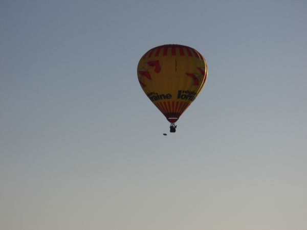
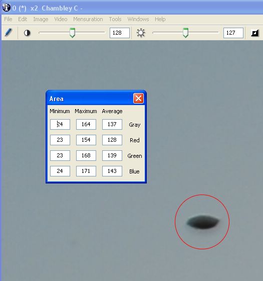
Illustration: the file which we have chosen to illustrate – as far as possible – the different steps of photo analysis, concerns an incident which took place during the hot-air balloons competition Mondial Air Ballon 2007 which was organized, as every year, on the former military base of Chambley-les-Bussières (Meurthe-et-Moselle, France) in August 2007.
One of the participants to this meeting, who had shot 120 photos with his Nikon D200 digital camera, selected one of them, dated 5 August, on which appeared, in the upper left corner, among hot-air balloons, a quite singular unidentified object.
This case was reported by Mr. Christian Comtesse, who conducted a thorough on-site investigation , the final conclusions of which will be presented at the end.
Here is the photo – which we shall analyze – as it appeared, as well as a zoom on the unidentified object:
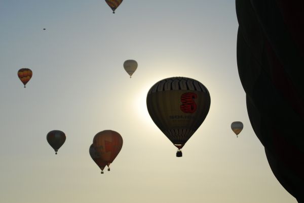
Photo from Chambley

Zoom on the unidentified object in Chambley
Spatio-temporal localization of the photo
The first required information for photo analysis concerns the place, date, and precise time of the shot.
According to the investigator’s needs, he may refine localization of the camera using, if necessary, a detailed map or a GPS receiver, in the frame of a possible in situ reconstitution.
As concerns dating, it is advisable to note down not only the local time, but also the universal time, the difference depending on both geographical location and current season.
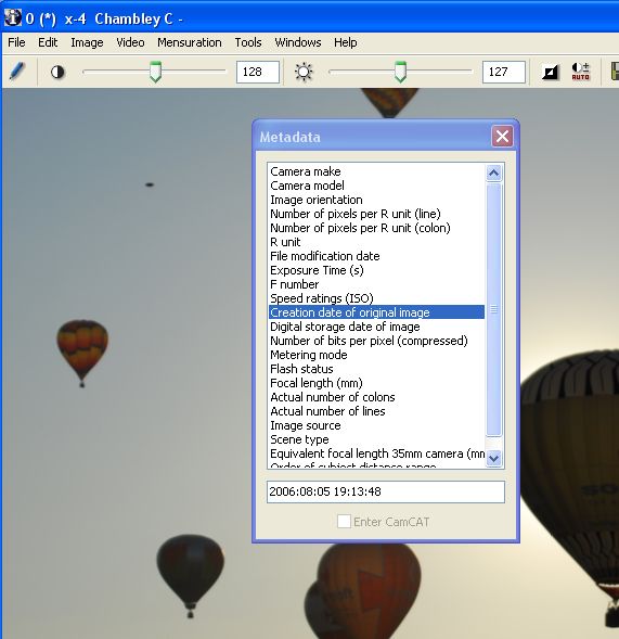
It is important to stick to a basic principle for mensuration in physics: for each parameter, it is not enough to collect the nominal value (longitude, latitude, time), but this must also be associated with an uncertainty value. In particular, as concerns shooting time, one should try to quantify the possible error range, according to each source of information (operator’s watch, date indicated in EXIF metadata, etc.) and, if required, to perform crosschecking and calibrations afterwards.
Illustration: in the Chambley case, all localization data in space (meeting place) and in time (19h14, local time) were spontaneously provided by the author of the photo – shot against the sunlight, at the end of the day, in very nice weather.
However we noted a disagreement on the year, between the testimony (2007) and the EXIF metadata (2006). This was most probably due to an initial manual data input error from the operator.
Environmental data
Environmental data to be searched have differing priorities, of course, from one case to another, depending in particular on shooting time (day or night).
Day outside
For a photo shot outside during the day, in particular if the phenomenon appears in the sky, it is useful to know the usual meteorological parameters: temperature, pressure, humidity, speed and direction of winds, horizontal visibility.
Such parameters will be collected from the usual sources, in particular: Weather Bureaux, surrounding airports and airfields.
Night outside
For a photo shot by night with a sufficiently clear sky, one shall obtain a plot of the star dome configuration as it appeared in the field of the camera at the time of shooting .
Several specialized software produce such plots, in accordance with the geographical coordinates of the shooting location and universal time.
In any case, if confusion is possible, one will try to collect information on air trafic, or forecasts for atmospheric re-entries (meteorites, space debris) at shooting time. The same thing as concerns non-conventional lights, such as laser beams pointed to the sky (carnival, rave-party, river boats, etc.) or sky lanterns (an increasing common cause of false reporting).
Data on the photographed scene
Depending on the circumstances and environment, one will try to identify elements appearing in the field – especially those which may be used for geometric or radiometric comparisons – and to assess their respective dimensions (size, distance from the camera, surface), in view of interpolating or extrapolating calculations, as well as characteristics in terms of luminance and color.
This may concern, for example, buildings, trees, relief, celestial bodies (sun, moon) or human beings.
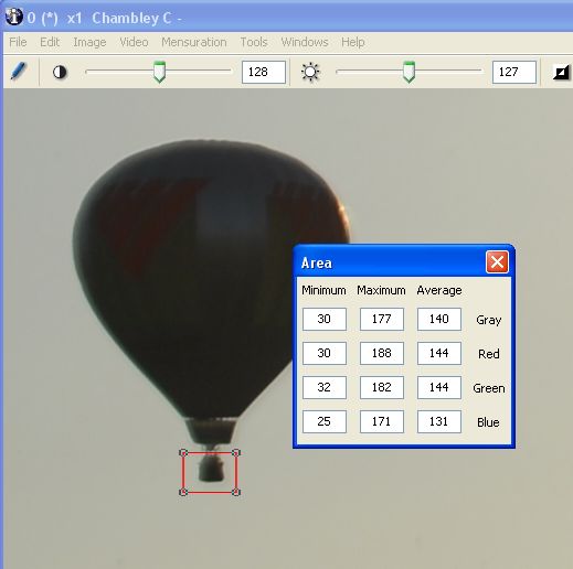
Illustration: the only visible elements of comparison in the scene photographed in Chambley are hot-air balloons. It was therefore important to make enquiries on the size of such objects.
Investigation on Internet taught us that a standard air-balloon has a volume in the order of 2500 m3, a height of 20 m and a diameter of 15 m.
Testimonies and other records
Self-evidently, all available information on the « case » under study must be gathered, so as to perform crosschecking, possible triangulation, estimation of size or speed, etc.
Note : It is useful to remember recommendations produced by the scientific session held in Pocantico in 1997, in the frame of an international colloquium about « Physical evidence associated to UFO testimonies ». In substance, it stated that a UFO file only deserves serious study if there are at least two independent sources of information.
This principle implies, in the case of a photo, that in order to justify its extensive analysis, there should exist at least a visual testimony or additional record – photographic or other – collected independently from that photo.
Illustration: the picture from Chambley became rapidly wellknown in ufological circles and in local press, which enabled investigators to gather several other photos taken during the same Mondial Air Ballon 2007 meeting. Several of those had apparently nothing to do (some of them being crazy), but there came out a second photo (below) which seemed to display exactly the same object, a little below the basket of a balloon.
Other photo from Chambley
Characteristics of the camera
All technical data of the camera as well as possible settings for the shot (focal length, focussing distance, exposure time) must be collected.
On the basis of a known camera model, it remains always possible to find out all characteristics, for if the operator himself does not have them to hand, the manufacturer can be consulted.
Besides, JPEG image files produced by digital cameras comprise, more and more systematically, metadata in the EXIF format, containing all required data on camera, date and settings. Access to original metadata, however, is only possible if the image file has not suffered any alteration.
Moreover, there exist a number of redundancies, and therefore means to regenerate pieces of data if they happen to be missing: for example, the real dimensions of the photosensitive array may easily be derived from the focal length conversion factor, when this parameter is available.
Illustration: the photo from Chambley has been obtained in its original format, which allowed recovery of EXIF metadata, on top of detailed technical information already provided by its author.
Camera settings
Parameters corresponding to settings possibly chosen by the operator should be collected from him as far as possible.
In addition, as already indicated, it is generally possible to find those data in metadata included in the image file.
In the particular case of focussing distance, if the operator remembers having shot while focussing on a given object, it is most useful to know or at least to estimate the real distance between that object and the camera, in view of accurate calculations on the depth of field.
Illustration: the photo from Chambley was shot from the ground, with a Nikon D200 digital reflex camera focussed to infinity, with an exposure time equal to 1/6400 sec.
Collecting image file and related metadata
As already explained, an image file should be collected in its original format, after it has undergone, as a maximum, nothing more than computer duplication, without any modification.
One will use different available media: preferably the memory stick of the camera (so as to be sure – in principle – that no transformation has been done outside that camera) or, if not, any other computer medium (e.g. USB stick, CD-Rom).
File generated by a digital camera
In order to access all the ancillary data comprised in the format, one will make use of specialized software. In the case – most of the time – of the EXIF format, there are numerous software solutions available to extract metadata, among which Exifer, GeoSetter, XnView, ACDSee, Imatch, PhotoME, and finally « IrfanView » (which, completed by the « EXIF » plug-in, has been recommended by the JPEG board).
We work with IPACO, which allows us simultaneously to display values of EXIF parameters present in an image, and to automatically exploit the same parameters for quick angular mensuration.
File generated by a cell phone
In the case of a photo generated by a cell phone, the first question is how to recover the image file in a computer.
Three transferring modes are possible, depending on cell phone models:
- Connection of an external memory stick, or Secure-Digital, readable through a card-reader connected with the computer.
- Direct transfer from the phone to the computer through a USB connection, provided either that type of connection works in Plug and Play, or the relevant software driver is available.
- Direct transfer from the phone to the computer through Bluetooth (radio waves on short distance).
More and more cell phone models equipped with a digital camera generate files in JPEG format, with EXIF metadata, which brings us back into the realm of standard digital cameras.
In the case of smartphones, a simple direct transfer through e-mail is proposed.
Authentication of the document
Coherence of physical data
Analysis of the testimony, and of its coherence with physical parameters of the document, is necessary in all cases. It may involve external specialized verification tools, such as METAR data for meteorology, Google Images for search of existing images, or Stellarium for astronomy.
Examination of coherence between shadows and lighting in the whole photo is also an indispensable prerequisite. It will consist, at first, in finding out luminous source(s), and in checking through a specialized tool like IPACO the coherence of their aspect and of their impact on form shadows and cast shadows.
Silver medium
There exist few crosschecking means, in an authentication process, between a silver photo and associated testimony, bearing in mind that the basic rule is to only work with original documents.
However, some pieces of information, inlaid in a film processed by a public laboratory, may prove useful to expose false evidence: on one hand the processing date, written on the edge of the film whilst on the other hand sequential numbering of film negatives, all of those data being a priori forgery-proof.
Digital medium
EXIF metadata
As already mentioned, it is essential to know the camera model used for the shot, as well as those settings possibly chosen by the operator, so as to determine the technical parameters needed for analysis. This information is in general provided by the ancillary data – or metadata – associated with the standard format of image files generated by a digital camera.
EXIF metadata are supported by all image file formats, except JPEG2000 and PNG. They contain many tags, corresponding to shooting date, technical characteristics of the camera, geolocalization, copyrights or external programmes used to modify the file (Photoshop, etc.).
The number of EXIF data effectively provided, as well as their layout, varies a lot from one camera model to the other, or even for a given camera, depending on the firmware used.
Unfortunately, study of those metadata is not sufficient by itself to demonstrate a possible fake. In fact, they are easy to modify and can even be completely replaced through the use of specialized software, such as EXIFer, EXIFtool, or a mere text editor in hexadecimal.
However a good approach as an initial exercise is to compare the EXIF data of the document under study with those extracted from another photograph shot with the same camera, if possible using the same firmware. In many cases, this simple verification will reveal use of a touch-up programme.
On a document that is not original, this approach has no intrinsic value, because there are so many ways to modify metadata unintentionally. However, with a first-hand original document (or claimed to be such by the witness), this may suffice to invalidate its authenticity.
Other metadata and markers
There exist many other metadata associated with digital photos/videos, more or less well known and easy to extract. Their exploitation by a specialized authentication tool, such as IPACO, allows the verification of whether the document is an original or not. If it is not, it will be the analyst’s task to determine whether data have been manipulated or not. For obvious reasons, we will not go here into further details.
File compression parameters
Most digital photos are stored in JPEG format, which makes use of compression algorithms with irreversible losses.
In practice, this results in a modification of quantification tables when there is an interaction with an external programme and/or a new file saving. Such a modification may be detected through the use of specialized software such as JPEGSnoop, which is able to extract all data relative to various formats and to compare them with an internal database containing the compression signatures of many digital cameras and software (as well as JPEG, it also takes into account AVI and MOV formats for videos, and numerous RAW image formats: NEF, THM, DNG…).
In most cases, the combined application of some or all of the above-described techniques applied to falsified documents will expose fakery.
Once an image file has been loaded onto his or her computer, the analyst may examine it and become familiar with it, with help of a specialized image viewing and processing software. By highlighting image details, an attempt will be made to establish parallels between this photo and already known cases, to detect possible clues and to establish some lines of thought, before initializing a deeper quantitative analysis.
The most useful image manipulation tools are also the most conventional ones: zoom, contrast enhancement, sharpness (high-pass) filtering, contour detection and the separation or enhancement of primary colors.
Many software tools may be used for such a work. The most well-known reference is Photoshop, an extremely powerful software in terms of interactive functionalities, essentially designed for photographers. A first approach is equally possible with simpler viewing tools, such as Irfanview.
The most appropriate solution is a CAPI tool, which, by definition, permits simultaneous interactive photo-interpretation (object of this paragraph) and quantitative analysis (the subject of the following paragraph), in a flexible and efficient approach. This is the case with IPACO.
Illustration: interactive manipulation of the photo from Chambley essentially consisted of zooming, taking advantage of the high resolution of the original document (10 megapixels).
At this point, one may imagine the object as possibly being a child’s balloon, or maybe a very big bird.
Geometric mensuration
Geometric mensuration on a digital photo relies on pixel localization in the image, which relate to the position of points of interest on the sensitive medium (the CCD array) and thus to the angular position of corresponding points in the scene.
A basic operation consists therefore in designating a point on the screen with a mouse, and in collecting its row and column coordinates. This can be done on the image, in full resolution (the image size then usually being larger than the screen, one will use the scroll boxes of the window to scroll it through), or making use of a zoom, which allows designation of a point of interest with better accuracy, sometimes to less than one pixel.
Coordinates of a point A in pixels are given in the form A {ia,ja}, with:
ia : column number, from left to right on the screen, comprised between 0 and H-1
ja : row number, from top to bottom on the screen, comprised between 0 and V-1
H : total number of columns (thus of horizontal pixels)
V : total number of rows (thus of vertical pixels)
Coordinates of the center of the photo P being P {(H-1)/2,(V-1)/2}, distances in pixels between P and two points A and B are:
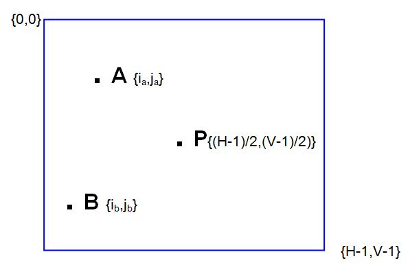
PA = √ { [ia - (H -1)/2]2 + [ja - (V-1)/2]2 }
PB = √ { [ib - (H -1)/2]2 + [jb - (V-1)/2]2 }
AB = √ { (ia - ib)2 + (ja - jb)2 }
Those distances in pixels may then be converted into physical distances on the photosensitive medium, simply by applying the rule of three, if real physical dimensions of that medium are available.
Dimensions of the photosensitive array may be directly obtained with the technical characteristics of the camera, or inferred from the focal length conversion factor (if it is provided), either with technical characteristics, or with EXIF metadata associated with the photo (depending on manufacturers).
One should keep in mind that this conversion factor is to be applied to the diagonal of the rectangular (or square) surface of the sensor. Generally, it corresponds to the ratio of the diagonal of a 24x36 mm standard silver format – i.e. 43,3 mm – to the diagonal of the CCD array of the digital camera.
From the physical dimensions on the sensitive medium and from the focal length, one may derive the calculation of angular dimensions. Then, possible estimates of absolute dimensions may be obtained (cf above).
Regarding the estimation of distance between the object under study and the camera, a few approaches (cf above) require radiometric measures or sharpness estimates. One should then address respectively the two following sections.
Illustration: the very relevant angular size mensuration on the photo from Chambley concerns the largest apparent dimension of the unidentified object (we shall refer to its « length ») and the hot-air balloons (we shall concentrate on the horizontal diameters of two of them).
The IPACO software permits direct calculation of such angular sizes in a few clicks, taking automatically advantage of available EXIF metadata. For the sake of illustration however, we shall go through the calculations step by step.
First, we interactively collect the coordinates of the 6 pixels designated in the image below (image size: 3872 columns, 2592 rows) :
Extremities of the unidentified object: A {550,371} B {582,368}
Side extremities of balloon 1: C {591,1753} D {841,1753}
Side extremities of balloon 2: E {1864,1288} F {2689,1288}
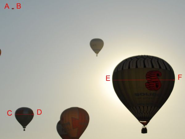
The calculation of angular size of the unidentified object is performed as follows, referring to above-mentioned formulas (where P is the center of the photo):
PA = √ { (550 – 1935,5)2 + (371 – 1295,5)2 } = 1666 pixels
PB = √ { (582 – 1935,5)2 + (368 – 1295,5)2 } = 1641 pixels
AB = √ { (550 – 582)2 + (371 – 368)2 } = 32 pixels
The focal length being equal to 80 mm (EXIF data), and the focal length conversion factor being equal to 1,5 (technical data of the camera), we are back to the case of a 24x36 mm camera with a focal length f = 120 mm (other EXIF piece of data called « Equivalent focal length 35mm camera »).
In that frame (24x36 mm), the effective dimension of one pixel equals:
36/3871 ≈ 24/2591 ≈ 0,00928 mm
thus:
a = PA = 15,46 mm
b = PB = 15,23 mm
d = AB = 0,30 mm
Applying the generalized Pythagoras’ theorem (cf above), we may calculate the angular size of the unidentified object:
δ object = arccos [(2x1202+15,462+15,232–0,302) / 2√{(1202+15,462)(1202+15,232)}]
δ object = 0,14 °
In the same way, we calculate the angular size (horizontal diameter) of both reference balloons:
δ balloon1 = 1,10 °
δ balloon2 = 3,65 °
Luminance estimation
Directly measurable data which quantify light collected by a given pixel of a digital photo are gray levels (in black and white) or respective brightness levels in the 3 primary colors (red, green, blue). Those values represent the apparent luminance of corresponding points in the scene, with certain limitations (cf above).
It is only possible, in this domain, to produce estimates and to sort objects according to increasing or decreasing values of their apparent luminance. Nevertheless, this may be enough to perform a rough interpolation and to estimate a range of possible distances between the object and the lens.
One will use, for this type of mensuration, an image viewing or processing software providing levels of a selected pixel on the screen through a mouse, or statistics on level values in a given image area graphically selected on the screen, or a plot of level variation along a designated vector (a radiometric cross-section).
Here are examples to illustrate these types of mensuration, using the IPACO software:
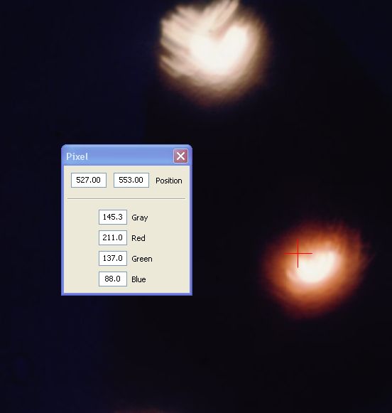
To the cursor position (red cross) correspond the coordinates (position) of the selected pixel, as well as its RGB levels (red, green, blue) and gray level (average of the 3).
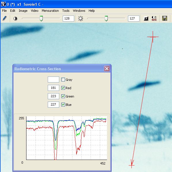
To the vector drawn on the right of the image (red arrow) correspond the plot of the radiometric cross-section showing variations of the levels (representing apparent luminance), displayed in the window.
Illustration: the photo from Chambley was shot against the sunlight and we may consider that the darkest parts of the objects of the scene were submitted to variations of their apparent luminance mostly due to atmospheric diffusion. Consequently, we shall concentrate on the dark part of the unidentified object, as well as that of both reference balloons.
In a quite empirical approach, we shall content ourselves with noting down the darkest pixel value in each of these three areas, using IPACO’s tool dedicated to the analysis of the radiometry of pixels within in a closed surface (here a red circle)..
Dark level object = 24
The same for both reference balloons’ baskets.
Balloon 1:
Balloon 2:
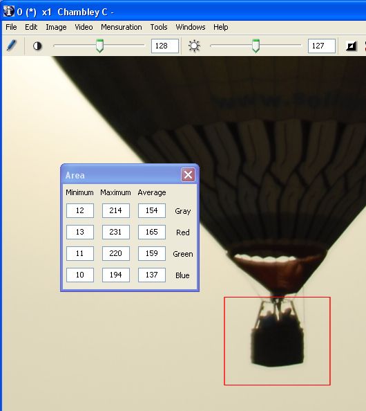
Dark level balloon1 = 30 Dark level balloon2 = 12
Assuming – which is highly probable – that the object and both reference baskets are really dark, we may conclude that the distance of the object from the camera was somewhere between that of balloon 1 and that of balloon 2. In fact, those distances may be estimated, if we assume that both balloons have a standard diameter Ф = 15 m (cf formula above):
Distance balloon1 = (Ф/2) / tan (δ ballon1 / 2) i.e.: Distance balloon1 = 391 m
Distance balloon2 = (Ф/2) / tan (δ balloon2 / 2) i.e.: Distance balloon2 = 118 m
Through linear interpolation on the darkest pixel values (an empirical approach), we obtain an estimate of the distance to the unidentified object:
Distance object = 300 m
From which we may derive an estimate of its actual length:
Length object = 2 x 300 tan (0,14°/2) i.e.:
Length object = 0,73 m
Taking into account uncertainties and calculation approximations, we can conservatively conclude that the length of the object – if it was actually dark – was somewhere between 50 cm and 1 m.
(Should its color have been - in reality - lighter, its length could only have been less than this estimate).
Sharpness estimation (FTM)
Sharpness estimation of the contours of an object, apart from the case of a movement blur (which must be analyzed case by case), may be used to assess the distance of that object, following two possible approaches.
On one hand, if the object was outside the depth of field, it appeared inevitably more blurred on the photo than objects located inside the depth of field. This is particularly the case for very small objects very close to the lens, especially if they are illuminated by the flash (see numerous photographs displaying « orbs »).
On the other hand, it is sometimes observed that, within the depth of field, the apparent sharpness of an object deteriorates progressively as the object moves away, because of atmospheric diffusion. The crossed atmosphere layer is characterized by its MTF, and behaves like a low-pass filter in the spatial frequency domain, this phenomenon being more or less measurable depending on weather conditions. Comparison of contours of the object under study and of other objects located at known or estimated distances from the camera then allows us to narrow the range of possible distance of the object.
The only simple empirical way to estimate the sharpness of a contour is to plot a radiometric cross-section (of the same nature as a densitometric cross-section in silver photography) perpendicular to that contour. Indeed, the spatial frequency spectrum is linked through Fourier transform, in the bidimensional image space, to the impulse response (image of a point light source), which in turn may be linked in a monodimensional form by the response, in a given direction, to the « step function » made of the discontinuity of an object’s contour.
In practice, the more the gray level transition curve, on either side of a contour, spreads over a large width (in other words: the shallower the transition slope), the more the image has been degraded by the MTF of the atmosphere, and therefore the farther away was the object (through a commensurately thicker atmospheric layer), all other things being equal.
Here again, it is often only possible to make an empirical interpolation between the « contour responses » of several objects in the scene, allowing to « sort » them by increasing distances from the camera.
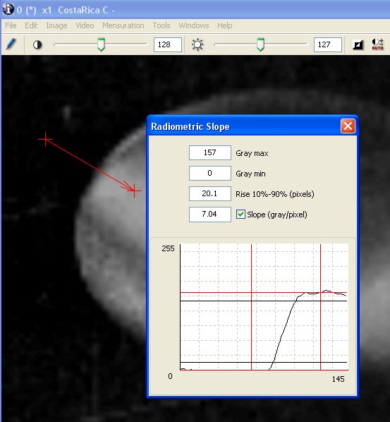
Estimate of radiometric slope along a designated vector, perpendicular to the contour of the object being analyzed : the transition slope is here estimated to 7,33 levels/pixel (transition from 10% to 90% over 19,7 pixels).
Illustration: weather conditions in Chambley, with an excellent visibility, do not allow detection of any degradation of the sharpness of contours by atmospheric diffusion (the maximum slopes of radiometric cross-sections perpendicular to the respective contours of the unidentified object and of both reference balloons are of the same order of magnitude).
Color comparison
Colorimetric analysis is a particularly complex domain, in which we shall restrict ourselves to two limited considerations.
In a quite macroscopic way, it sometimes happens for a photo to clearly display a scene with a predominant color (blue, green, magenta, etc.). If an unidentified object is visible on that same photo, but shows a quite different predominant color, it is highly probable that the image results from a fake inlay. Indeed, for a small object with strongly predominant magenta to appear in a scene having strongly predominant green, for instance, it would be necessary that luminous energy emitted by this object be quasi-infinite (otherwise, its own color could only appear gray or white).
In another context, color information concerning an unidentified object may prove useful to support or contradict the assumption of a given type of emitted energy (propulsion mode for example), or to reveal a connected physical phenomenon, such as air ionization.
Possible contribution of texture
If the angular size of the object being analyzed is large enough, and if it displays at least one homogeneous side, that side may be characterized by a particular texture, which may be highlighted by a zoom and/or a high-pass filter (thus enhancing contrast).
Such a texture may then be compared to texture catalogs, containing characteristics of various materials.
Reality of an external stimulus
The existence of a physical stimulus outside of the camera will be established through the elimination of various possible internal causes.
Some common internal causes may be listed, starting from the already known list for silver photos (with the exception of mechanical or chemical problems of the film, which have no equivalent in digital photography):
Multiple exposure (superimposition of 2 or more shots): this problem, accidental or deliberate, sometimes occurs in silver photography, and can be identified by thorough examination (under a microscope) of the layout and the size of the grains in the film (which increases with the number of exposures). But apart from a few camera models, which offer the possibility of deliberate multiple exposure, this type of accident is, most of the time, technically ruled out in digital photography.
Spurious optical reflections: according to the optical block configuration in the camera, and to the presence or not of an anti-reflective layer on the lens, spurious reflections may sometimes appear near a light source on a photo, often with a polygonal contour (diaphragm). These are generally easy to identify.
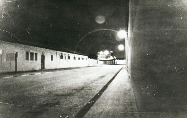
There are also, in the presence of powerful light sources (sun, spotlight), cases of multiple complex reflections generating spurious smooth luminous shapes, sometimes resembling mathematical curves called caustics. Those reflections (or « flares ») can be recognized by the fact they appear symmetric to the light sources, with respect to the optical center of the photo.
The photo displayed below, shot by night in a street of Toulon (France), shows an unusual accumulation of optical effects.
Light leak: when the shutter of the camera has a closing defect, it can let some light leak, which results in photos where a light trail appears with a random shape (depending on the operator’s movements just after the shot) seeming to originate from a light source. This trail even appears as a dotted line when the source is a bulb fed in alternating current (50 or 60 Hz) and the operator’s movement has been fast enough.
Lack of lens cleanliness: for the record, if the lens is dirty or scratched, photos may bee degraded, in particular in sharpness (the MTF of the lens being degraded). The state of the lens should always be checked a posteriori.
Defective pixel(s): in a digital camera, it may be that one pixel is damaged, producing systematically a black point in the same place of each picture. This type of problem is easy to identify through cross-checking several photos shot with the same camera.
Defects specifically generated by the compression algorithm of digital images (JPEG format) essentially affect color and generally consist in moiré effects on relatively even surfaces.
Photographic montages obtained by inlaying into the image one or several external elements belong, of course, to cases where no real stimulus was present in the scene.
Evidence of this type of hoax must rely on coherence criteria: luminance, color, albedo, sharpness (MTF), shadows, plus possible movement blur from the operator.
Illustration: regarding the photo from Chambley, we may easily reject all the usual manipulation errors, as well as the fake hypothesis. We consider the camera technology, the cooperative behaviour of the author and – mainly – the existence of at least one other photo, shot independently, the analysis of which (not reproduced here) shows a strong coherence with already mentioned quantitative estimates.
Effective presence of a material object in the field
The effective presence or not of a material object in the scene will be established through possible clues proving the concrete reality of that object (dark color, cast shadow, lighting of the object - coherent with the scene - by the sun, the moon or any artificial source).
If an object was effectively in the field of view, i.e. inside an observation solid angle the vertex of which was the center of the lens, it could be or not be inside the depth of field, which sets the distance range inside which elements of the scene appear sharp on the photo.
For this reason, one will first analyze the sharpness (MTF) of contours.
Illustration: the photo from Chambley shows a dark object, which definitely eliminates a purely luminous phenomenon.
All visible objects in the photographed scene were sufficiently remote from the camera, which was focussed to infinity, to make certain that they were inside the depth of field.
Object outside the depth of field
If the camera was focussed on a short distance, the depth of field extended between two finite limits, which may be estimated from the characteristics and settings of the camera. A remote object may, in that case, appear blurred, which indicates that its distance was larger than the maximum of the depth of field, in particular if other visible objects allow comparisons.
Most of the time, focus is set (in a fixed way or by the operator) to infinity. Only objects that are nearer the lens than the minimum of the depth of field may appear blurred (except movement blur, which affects the whole scene). This is the case in particular for « orbs »: those white circular spots which correspond most of the time to hanging dust, droplets or insects in front of the lens, illuminated by the flash (See illustration below).
This type of blurred circular spot appears more frequently with digital cameras, because the depth of field is greater than in silver film cameras, and particularly with compact models, where the flash is geometrically closer to the lens, and lights all dust and other small particles and insects around.
Object inside the depth of field
If the object under study appears sharp, we know it was inside the depth of field. This allows us to derive, from its angular size, a range of possible size (if the depth of field has a maximum) or a minimum size (if the depth of field extends to infinity).
Nature of an identified phenomenon
If the object or phenomenon turns out to be probably identified, one should try to perform objective mensuration and cross-checking in order to reach a formal conclusion.
The impeccable quality of such a demonstration is of paramount importance, because filing a case as « identified phenomenon » has a strong conclusive and final nature, contrary to filing it as « unidentified », which always remains – by definition – open to further modification.
Illustration: the object photographed in Chambley has not been formally identified [this was written in 2008], but it could well be a child’s slightly deflated balloon, or maybe a very big bird. Only a deep on-site investigation would determine whether each of those two hypothesis is credible.
Characteristics of an unidentified phenomenon
If it is not possible to determine the nature of the object under study, the photo may provide elements for its characterization: geometry (size, shape), photometry (light emitted, transmitted or reflected), color, texture, speed, acceleration.
Let us remind ourselves, at this point, of the great scientific interest one could expect from spectral information richer than that of a simple color photograph, about the light coming from a UFO, in particular if the object seems to emit its own energy (cf Note).
Case of a digital video document
Analysis of a video document requires a software tool allowing not only the viewing of the document, but also giving access to basic functionalities:
- Slow motion, frame by frame, freeze frame
- Extraction of a selected frame or sequence of frames for static analysis
- Frame deinterlacing.
The original video file will be loaded on computer and carefully scrutinized, with regard to a first step consisting of selecting one or several frames particularly rich in information, which will allow analysis to commence using the same tools as for still photos.
If the speed of observed movements so requires, one may proceed with deinterlacing a few key frames, so as to allow a finer time analysis.
If movements of the object are significant, one may proceed with angular transverse velocity and acceleration estimation.
If moreover conditions are right, as seen above, for the distance between object and camera to be known or estimated, it will be possible to derive estimates of the object’s actual size, transverse velocity and acceleration.
During dynamic analysis of the video, one will also be in a position to evaluate, if applicable, possible size, shape or color changes.
A few months after official delivery to CNES/GEIPAN of the initial version of this report, on-site investigations conducted by Mr. Comtesse did succeed: the photographed object was actually a big child’s balloon, perfectly identified, the size and distance of which were matching , but for a few percents, our conclusions of the photographic analysis.
Final report from Mr. Comtesse (in French)
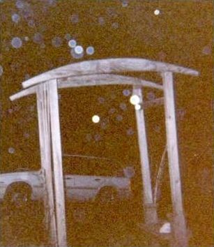
Strange luminous flares may sometimes appear on a photograph (particularly one shot at night). These are the result of spurious light reflections in the camera’s lenses. Each of these flares originates from a light source, which is normally within the field of view and therefore visible on the picture (in rare cases, however, the light source may be just outside this field). The characteristic of a lens flare is that it is located, in the picture’s plane, on a straight line connecting the photograph’s optical center with the light source.
Most of the time, a picture’s optical center matches its geometrical center. It is then a simple matter, in order to check whether a luminous spot is a lens flare, to draw a straight line between this spot and the picture’s center, and to see whether this line crosses a light source. If several lens flares are visible on the same picture, the cluster of lines which link them respectively with the center crosses all the light sources from which they originate.

There may be the case that a straight line which links a luminous spot with the picture’s geometrical center does not exactly cross a light source. If there are other spots suspected to be lens flares, it is possible to localize the optical center (which, in this case, is shifted from the geometrical center). This can be achieved by interactively changing the position of the « center » and observing the resulting movements of the cluster of lines which link it with the different spots. If a position is empirically determined for the optical center, such that each line of the cluster links a spot with a light source, it is then evident that these spots are lens flares.

Suspension thread
Uncovering a classic type of hoax, produced by shooting a model hanging by a thread, is sometimes tricky or even impossible, depending on the thinness of the thread as well as on its distance from the camera. In certain cases, classic image processing tools (contrast enhancement, high-pass filtering) do enable visualization of the thread, but this approach often proves to be inadequate.
An original and more powerful method may be used, in particular if, in the area where the thread could be present, the sky’s background is relatively uniform and may be compared to « noise » (i. e. noise from atmospheric diffusion and/or digitization noise). This method consists of increasing the signal-to-noise ratio by summing columns of pixels parallel to the suspectef thread, in a chosen area above the alleged UFO.
The following steps utilizing the Vertical thread tool implemented in IPACO were applied to one of the well-known photographs from McMinnville:
- Designate a vertical rectangle above the alleged UFO, covering the area where a thread is suspected to be present. A curve is displayed in a window, showing the mean value of pixels in each column of the rectangle.

- Slide the cursor along the rectangle’s lower side in the image and monitor the vertical bar at the corresponding position of the curve. Position the cursor at the location of the supposed attachment point of the thread. If there is a thread perfectly vertical with reference to the picture, and if the obtained increase of the signal-to-noise ratio is sufficient, the curve displays a peak in front of the bar, which is positive or negative depending on compared gray level of the thread and that of the sky’s background. The mean value of the pixels of the column corresponding to the bar’s position is permanently displayed, as well as the difference between this value and the curve’s mean, normalized by the standard deviation (number of sigma).

- In general, however, a suspension thread is typically not strictly parallel to the picture’s vertical axis, thus nothing significant appears at this stage. The tool, however, enables the reference rectangle to be tilted by an angle between -30° and +30° from the vertical. More precisely, the rectangle is changed into a parallelogram, the lower side of which remains fixed and the height constant. The pixel summing columns are also tilted by the same angle, with the curve changing as the angle is modified.
- It is then possible to check whether an angle exists for which a significant peak appears in front of the supposed location of the attachment point. Such a peak indicates the probable existence of a thread, especially if the difference between this peak and the mean value is noticeably significant.

- If the curve shows slow variations, for instance due to vignetting, it is possible to get rid of them through spatial high-pass filtering, obtained by subtracting from it a copy of the same curve, previously smoothed by a low-pass spatial frequency filter (convolution by a rectangular window). This provides a more significant standard deviation value.

- If such a peak is indeed present, the tool may then launch an automatic optimization which will accurately tune the tilt angle and the bar’s position, so as to obtain a maximum value between the peak and the curve’s mean value.
- If the results tend to confirm the existence of a thread, the tool also enables an extra verification to be performed as a cross-check. Based on the most probable straight line for the thread’s location and also on the supposed position of the attachment point on this line, a circular scanning is performed around this point: pixels of the columns taken into account for the summation are those contained in the parallelogram. A second curve is then displayed in the window, showing the mean value of each column’s pixels during the scanning. If another peak appears, corresponding to the previously found angle, the probability of existence of a thread is doubly established, especially if the difference between the new peak and the second curve’s mean value is significant.

Chinese lanterns are today one of the major sources of confusion. In order to help the analyst recognize this type of light source on a night photo/video, a specific tool has been implemented in IPACO. This tool does not produce a formal proof, but it gives an invaluable indication of the probability of an explanation being provided by the presence of a Chinese lantern.
The principle consists of designating the light source, computing the mean RGB levels of those pixels of the source that are not saturated, correcting from the sky background values around and deriving the mean chromaticity of these pixels. This mean value of the chromaticity is then displayed in the « Maxwell triangle » and compared to characteristic zones of certain types of light sources (lanterns, stars/planets, aircrafts…). These zones have been built up from a large number of night pictures of the sky showing light sources the nature of which is known, using a large variety of cameras or smartphones with different settings. It will be possible to refine these with growing exploitation of this technique.
If the mean chromaticity of the light source under study only falls within the « Lantern zone », the likely explanation is provided by it being due to a lantern. If it falls within the « Lantern zone » and also within one of the other zones, the explanation is deemed possible. Finally if it falls totally outside of the « Lantern zone », the explanation is presented as of it being unlikely.


SUMMARY
Authenticity of the document under analysis
Establishment of origin of image under analysis
Physical presence of a material object in the scene
Identification of a phenomenon
Characterization of an unidentified phenomenon
TWO COMPLEMENTARY TECHNICAL APPROACHES
Qualitative analysis (Photo-interpretation)
Quantitative analysis (mensuration and estimation)
General environment of the picture
MEASURABLE PARAMETERS ON A PHOTO
Frame accumulation (summation)
PRACTICAL ANALYSIS METHODOLOGY
Authentication of the document
Reality of an external stimulus
Effective presence of a material object in the field
Nature of an identified phenomenon
Characteristics of an unidentified phenomenon
Case of a digital video document